일단 code review를 하면서 중요한 부분은 논문에 존재하는 알고리즘에 대한 이해이므로,
다른 부분은 제외하고 논문에 나오는 알고리즘 부분에 치중하여 보기로 하였다.
그리고 다음 블로그의 내용을 위주로 진행했다.
1. IMU pre-integration Theory
먼저 논문에 있는 내용을 이야기해보자면 IMU 센서의 데이터에 대한 수식은 다음과 같이 표현될 수 있다.

여기서 a^ 과 w^은 imu 센서로부터 얻을 수 있는 raw data이다.
raw data에는 bias와 noise가 포함되게 되는데, 이를 ba, bw 그리고 na nw 로 나타내게 된다.
그리고 가속도에는 중력가속도 또한 포함되므로 이는 gw로 나타내게 된다.
그리고 각각의 bias와 noise는 가우시안으로 표현될 수 있다.
기본적으로 IMU pre-integration이 아니라 IMU integration에서는 영상 프레임 bk 와 bk+1 사이의 위치, 속도, 회전 변화, 즉 pbk_1, vbk+1, qbk_1은 다음과 같이 이전 프레임의 위치, 속도, 회전인 pbk, vbk, qbk와 bk에서 bk+1 동안의 IMU 센서의 데이터를 통해 계산하게 된다.

하지만 논문에서 언급하다 시피, IMU 센서의 빠른 데이터값들을 매번 받아서 PVQ 값을 계산하는것은 너무 연산소모적이므로, bias의 변화 값이 클 때만 PVQ 연산을 진행하도록 한다. bias의 변화 값이 작을 때는 PVQ 연산을 진행하지 않으며, first-order approximation을 통해 bias의 변화량만을 추정하게 된다.
이를 위해서는 bias와 관련된 수식이 필요한데, 이를 해결하기 위하여 위 식의 양 변에 R을 곱해 우변에 bk의 데이터와 imu 센서의 데이터 값들만 남겨주게 된다. (quaternion에서는 q를 곱하게 된다.)
이때, 오른쪽에 알파, 베타, 람다가 남게 되는데 이 녀석들은 다른게 아니라 IMU 센서의 노이즈가 포함된 값들을 의미하는 것으로 보면 된다. 그리고 우리의 목적은 IMU pre-integration을 통해 이 알파, 베타, 람다 값들을 계속적으로 구해주게 된다.

위 수식에서 좌항에 R(bk,w) 가 곱해지면서 PVQ가 P(bk,bk+1), V(bk,bk+1), Q(bk,bk+1)를 구할 수 있게 된다.
우항의 괄호안의 내용들은 integration 과정에서 필요하지 않은 내용들이다. 그러므로 알파, 베타, 람다에 대해서만 나타내면 다음과 같이 나타낼 수 있다.
우항의 괄호안의 내용들은 integration 과정에서 필요하지 않은 내용들이다. 그러므로 알파, 베타, 람다에 대해서만 나타내면 다음과 같이 나타낼 수 있다.

다변수 벡터함수에 대한 미분은 Jacobian Matrix를 이용해 수행할 수 있음. 이를 사용하면 알파, 베타, 람다를 first-order taylor expansion을 이용해 추정할 수 있음. 식은 다음과 같아짐.

이에 관한 코드는 다음 부분에서 살펴보기로 함.
1-(1). Evaluate()
evaluate는 이전 프레임과 현재 프레임의 P, V, Q, ba, bw 를 비교해 pre-integration을 해야할지 판단하는 부분으로 vins_estimator/src/factor/imu_factor.h에서 사용되며, vins_estimator/src/factor/integration_base.h 에서 확인할 수 있다.
1
2
3
4
5
6
7
8
9
10
11
12
13
14
15
16
17
18
19
20
21
22
23
24
25
26
27
|
Eigen::Matrix<double, 15, 1> evaluate(const Eigen::Vector3d &Pi, const Eigen::Quaterniond &Qi, const Eigen::Vector3d &Vi, const Eigen::Vector3d &Bai, const Eigen::Vector3d &Bgi,
const Eigen::Vector3d &Pj, const Eigen::Quaterniond &Qj, const Eigen::Vector3d &Vj, const Eigen::Vector3d &Baj, const Eigen::Vector3d &Bgj)
{
Eigen::Matrix<double, 15, 1> residuals;
Eigen::Matrix3d dp_dba = jacobian.block<3, 3>(O_P, O_BA);
Eigen::Matrix3d dp_dbg = jacobian.block<3, 3>(O_P, O_BG);
Eigen::Matrix3d dq_dbg = jacobian.block<3, 3>(O_R, O_BG);
Eigen::Matrix3d dv_dba = jacobian.block<3, 3>(O_V, O_BA);
Eigen::Matrix3d dv_dbg = jacobian.block<3, 3>(O_V, O_BG);
Eigen::Vector3d dba = Bai - linearized_ba;
Eigen::Vector3d dbg = Bgi - linearized_bg;
Eigen::Quaterniond corrected_delta_q = delta_q * Utility::deltaQ(dq_dbg * dbg);
Eigen::Vector3d corrected_delta_v = delta_v + dv_dba * dba + dv_dbg * dbg;
Eigen::Vector3d corrected_delta_p = delta_p + dp_dba * dba + dp_dbg * dbg;
residuals.block<3, 1>(O_P, 0) = Qi.inverse() * (0.5 * G * sum_dt * sum_dt + Pj - Pi - Vi * sum_dt) - corrected_delta_p;
residuals.block<3, 1>(O_R, 0) = 2 * (corrected_delta_q.inverse() * (Qi.inverse() * Qj)).vec();
residuals.block<3, 1>(O_V, 0) = Qi.inverse() * (G * sum_dt + Vj - Vi) - corrected_delta_v;
residuals.block<3, 1>(O_BA, 0) = Baj - Bai;
residuals.block<3, 1>(O_BG, 0) = Bgj - Bgi;
return residuals;
}
| cs |
Eigen::Matrix<double, 15, 1> evaluate(
const Eigen::Vector3d &Pi, const Eigen::Quaterniond &Qi, const Eigen::Vector3d &Vi, const Eigen::Vector3d &Bai, const Eigen::Vector3d &Bgi,
const Eigen::Vector3d &Pj, const Eigen::Quaterniond &Qj, const Eigen::Vector3d &Vj, const Eigen::Vector3d &Baj, const Eigen::Vector3d &Bgj
)
15행 1열 의 Matrix 자료형을 가진 evaluate 함수를 만든다.
파라미터로는 위치 P, 회전 Q, 속도 V, 그리고 가속도 바이어스 ba, 회전 바이어스 bg 가 존재한다.
그리고 i와 j를 붙여 bk 에서의 값과 bk+1 에서의 값으로 구분해준다.
Eigen::Matrix<double, 15, 1> residuals;
residuals 은 잔류의 의미이다. 그러므로 IMU 센서의 측정 후 에러값이 저장될 것이다.
Eigen::Matrix3d dp_dba = jacobian.block<3, 3>(O_P, O_BA);
Eigen::Matrix3d dp_dbg = jacobian.block<3, 3>(O_P, O_BG);
Eigen::Matrix3d dq_dbg = jacobian.block<3, 3>(O_R, O_BG);
Eigen::Matrix3d dv_dba = jacobian.block<3, 3>(O_V, O_BA);
Eigen::Matrix3d dv_dbg = jacobian.block<3, 3>(O_V, O_BG);
해당 부분은 jacobian을 만드는 부분이다. 아래의 수식에서 J 와 관련된 5개의 항을 만드는 것이다.
jacobian은 15x15 크기의 Matrix이다. 그리고 각 state 값의 정의는 다음과 같다.
O_P = 0,
O_R = 3,
O_V = 6,
O_BA = 9,
O_BG = 12
그러므로 3x3 크기의 블럭만큼을 (x, y)를 시작점으로 해서 가져오는 것이다.
Eigen::Vector3d dba = Bai - linearized_ba;
Eigen::Vector3d dbg = Bgi - linearized_bg;
이 부분은 bk+1 에서 측정된 IMU 센서의 값에서 bk 에서 측정된 IMU 센서의 값을 빼주는 것이다. 수식으로 보면 아래 매트릭스의 오른쪽 4번 5번 행의 값과 같다.

Eigen::Quaterniond corrected_delta_q = delta_q * Utility::deltaQ(dq_dbg * dbg);
Eigen::Vector3d corrected_delta_v = delta_v + dv_dba * dba + dv_dbg * dbg;
Eigen::Vector3d corrected_delta_p = delta_p + dp_dba * dba + dp_dbg * dbg;
해당 부분은 Jacobian과 bias를 이용한 계산으로 얻어낸 first-order approximation 값들이다. 만약 IMU bias가 천천히 변하게 된다면, 해당 수식을 이용해 pre-integration을 하게 되는 것이다. 수식은 아래와 같다.
residuals.block<3, 1>(O_P, 0) = Qi.inverse() * (0.5 * G * sum_dt * sum_dt + Pj - Pi - Vi * sum_dt) - corrected_delta_p;
residuals.block<3, 1>(O_R, 0) = 2 * (corrected_delta_q.inverse() * (Qi.inverse() * Qj)).vec();
residuals.block<3, 1>(O_V, 0) = Qi.inverse() * (G * sum_dt + Vj - Vi) - corrected_delta_v;
residuals.block<3, 1>(O_BA, 0) = Baj - Bai;
residuals.block<3, 1>(O_BG, 0) = Bgj - Bgi;
return residuals;
우리는 이미 앞에서 P(bk,bk+1), V(bk,bk+1), Q(bk,bk+1)를 구하는 수식을 확인했다.
위 수식의 우항의 알파, 베타, 람다는 이미 위의 과정에서 구했으므로 이를 이용하여 최종적으로 아래의 IMU measurement 모델이 만들어지게 된다. 위 수식의 우항의 알파, 베타, 람다 만 남기고 모두 좌항으로 이항했다고 보면 된다.
2. Discrete Theory

우리의 목표는 바로 이전의 수식처럼 bk와 bk+1 사이의 알파^, 베타^, 람다^ 를 구하는 것이다. 그리고 위 그림과 같이 IMU 센서의 frequency는 Vision의 frequency보다 훨씬 빠르다. 이를 해결하기 위해 다음 과정이 진행된다. 먼저 매 순간 시간 간격이 i라고 하였을 때, 가속도의 평균과 회전속도의 평균에 대한 식은 다음과 같다.

그리고 이를 알파^, 베타^, 람다^ 의 i+1 값을 추정하고자 한다면 다음과 같은 식이 된다.

그러니까 IMU pre-integration은 k, k+1 간격으로 진행하고,
Discrete form의 경우엔 k와 k+1의 사이에서 i라는 시간 간격으로 진행하는 것이다.
위 내용은 여러부분에서 코드로 나타난다.
2-(1), 2-(4), 2-(5) 가 그러하다.
2-(1). predict()
predict 함수는 위에서 설명했듯이 high frequency로 전달되는 IMU 데이터를 처리하기 위한 부분으로써, vins_estimator/estimator_node.cpp의 imu_callback 함수에서 사용되는 것을 확인할 수 있다.predict 함수의 코드는 다음에서 확인할 수 있다. (vins_estimator/estimator_node.cpp)
1
2
3
4
5
6
7
8
9
10
11
12
13
14
15
16
17
18
19
20
21
22
23
24
25
26
27
28
29
30
31
32
33
34
35
36
37
|
void predict(const sensor_msgs::ImuConstPtr &imu_msg)
{
double t = imu_msg->header.stamp.toSec();
if (init_imu)
{
latest_time = t;
init_imu = 0;
return;
}
double dt = t - latest_time;
latest_time = t;
double dx = imu_msg->linear_acceleration.x;
double dy = imu_msg->linear_acceleration.y;
double dz = imu_msg->linear_acceleration.z;
Eigen::Vector3d linear_acceleration{dx, dy, dz};
double rx = imu_msg->angular_velocity.x;
double ry = imu_msg->angular_velocity.y;
double rz = imu_msg->angular_velocity.z;
Eigen::Vector3d angular_velocity{rx, ry, rz};
Eigen::Vector3d un_acc_0 = tmp_Q * (acc_0 - tmp_Ba) - estimator.g;
Eigen::Vector3d un_gyr = 0.5 * (gyr_0 + angular_velocity) - tmp_Bg;
tmp_Q = tmp_Q * Utility::deltaQ(un_gyr * dt);
Eigen::Vector3d un_acc_1 = tmp_Q * (linear_acceleration - tmp_Ba) - estimator.g;
Eigen::Vector3d un_acc = 0.5 * (un_acc_0 + un_acc_1);
tmp_P = tmp_P + dt * tmp_V + 0.5 * dt * dt * un_acc;
tmp_V = tmp_V + dt * un_acc;
acc_0 = linear_acceleration;
gyr_0 = angular_velocity;
}
| cs |
void predict(const sensor_msgs::ImuConstPtr &imu_msg)
해당 함수는 파라미터로 imu 메세지를 받는다.
double t = imu_msg->header.stamp.toSec();
if (init_imu)
{
latest_time = t;
init_imu = 0;
return;
}
double dt = t - latest_time;
latest_time = t;
그리고 메세지의 시간을 이용해 이전의 메세지로부터 얼마나 시간이 걸렸는지 구한다.
double dx = imu_msg->linear_acceleration.x;
double dy = imu_msg->linear_acceleration.y;
double dz = imu_msg->linear_acceleration.z;
Eigen::Vector3d linear_acceleration{dx, dy, dz};
double rx = imu_msg->angular_velocity.x;
double ry = imu_msg->angular_velocity.y;
double rz = imu_msg->angular_velocity.z;
Eigen::Vector3d angular_velocity{rx, ry, rz};
그리고 메세지의 각 값들을 Eigen::Vector3d 형태로 만들어준다.
Eigen::Vector3d un_acc_0 = tmp_Q * (acc_0 - tmp_Ba) - estimator.g;
이 부분은 아래 수식에서 위의 가속도 평균을 구할 때, 우항의 괄호 안 내용 중 왼쪽의 이전 가속도 값에 대한 수식이 된다. 아마 estimator.g는 중력가속도인 것 같다.
Eigen::Vector3d un_gyr = 0.5 * (gyr_0 + angular_velocity) - tmp_Bg;
해당 부분은 위 수식에서 회전 가속도의 평균을 구하는 내용이다.
tmp_Q = tmp_Q * Utility::deltaQ(un_gyr * dt);
tmp_Q를 업데이트 한다.
Eigen::Vector3d un_acc_1 = tmp_Q * (linear_acceleration - tmp_Ba) - estimator.g;
위 수식의 가속도 평균에서 우항의 괄호 안의 오른쪽에 존재하는 현재 수신한 가속도 값이다.
Eigen::Vector3d un_acc = 0.5 * (un_acc_0 + un_acc_1);
이를 이용해 최종적으로 위 수식의 가속도 평균 계산이 된다.
tmp_P = tmp_P + dt * tmp_V + 0.5 * dt * dt * un_acc;
tmp_V = tmp_V + dt * un_acc;
아래의 수식과 같이 계산을 진행한다.
acc_0 = linear_acceleration;
gyr_0 = angular_velocity;
현재의 센서 데이터를 이전의 센서 데이터 변수에 넣어준다.
2-(2). getMeasurements()
getMeasurements() 함수는 IMU 센서의 측정 데이터를 이미지 프레임의 타이밍에 맞게 맞추는 역할을 하며, 함수를 살펴보면 다음과 같다. (vins_estimator/estimator_node.cpp)
1
2
3
4
5
6
7
8
9
10
11
12
13
14
15
16
17
18
19
20
21
22
23
24
25
26
27
28
29
30
31
32
33
34
35
36
37
38
39
|
std::vector<std::pair<std::vector<sensor_msgs::ImuConstPtr>, sensor_msgs::PointCloudConstPtr>>
getMeasurements()
{
std::vector<std::pair<std::vector<sensor_msgs::ImuConstPtr>, sensor_msgs::PointCloudConstPtr>> measurements;
while (true)
{
if (imu_buf.empty() || feature_buf.empty())
return measurements;
if (!(imu_buf.back()->header.stamp.toSec() > feature_buf.front()->header.stamp.toSec() + estimator.td))
{
//ROS_WARN("wait for imu, only should happen at the beginning");
sum_of_wait++;
return measurements;
}
if (!(imu_buf.front()->header.stamp.toSec() < feature_buf.front()->header.stamp.toSec() + estimator.td))
{
ROS_WARN("throw img, only should happen at the beginning");
feature_buf.pop();
continue;
}
sensor_msgs::PointCloudConstPtr img_msg = feature_buf.front();
feature_buf.pop();
std::vector<sensor_msgs::ImuConstPtr> IMUs;
while (imu_buf.front()->header.stamp.toSec() < img_msg->header.stamp.toSec() + estimator.td)
{
IMUs.emplace_back(imu_buf.front());
imu_buf.pop();
}
IMUs.emplace_back(imu_buf.front());
if (IMUs.empty())
ROS_WARN("no imu between two image");
measurements.emplace_back(IMUs, img_msg);
}
return measurements;
}
| cs |
std::vector<std::pair<std::vector<sensor_msgs::ImuConstPtr>, sensor_msgs::PointCloudConstPtr>>
getMeasurements()
먼저 함수는 IMU 데이터와 특징점 검출을 통해 얻은 Vision 데이터를 파라미터로 받는다.
std::vector<std::pair<std::vector<sensor_msgs::ImuConstPtr>, sensor_msgs::PointCloudConstPtr>> measurements;
IMU 데이터와 Vision 데이터를 담을 벡터 변수 measurements를 만든다.
while (true)
{
if (imu_buf.empty() || feature_buf.empty())
return measurements;
일단 각 buffer가 비어있는지 확인한다. 하나라도 비어있다면 아무 정보도 담기지 않은 measurements를 return한다.
if (!(imu_buf.back()->header.stamp.toSec() > feature_buf.front()->header.stamp.toSec() + estimator.td))
{
//ROS_WARN("wait for imu, only should happen at the beginning");
sum_of_wait++;
return measurements;
}
imu_buf.back()은 imu의 마지막 데이터를 의미하고, feature_buf.front()는 feature의 첫 데이터를 의미한다. estimator.td 는 두 feature frame 간의 시간인듯 하다.
즉, feature + td 보다 imu의 마지막 데이터를 받은 시간이 빠르다면, 아직 충분한 imu 데이터를 수신하지 못했다는 내용이므로, sum_of_wait을 증가시키고 아무 값 없는 measurements를 return한다.
if (!(imu_buf.front()->header.stamp.toSec() < feature_buf.front()->header.stamp.toSec() + estimator.td))
{
ROS_WARN("throw img, only should happen at the beginning");
feature_buf.pop();
continue;
}
만약 imu의 첫 데이터가 feature + td 보다 늦게 받아졌다면 feature_buf에서 가장 오래된 데이터를 하나 없앰으로써 feature의 시간을 증가시킨다.
sensor_msgs::PointCloudConstPtr img_msg = feature_buf.front();
feature_buf.pop();
img_msg에 feature_buf.front()를 담아준 뒤, feature_buf 에서 front는 빼준다.
std::vector<sensor_msgs::ImuConstPtr> IMUs;
while (imu_buf.front()->header.stamp.toSec() < img_msg->header.stamp.toSec() + estimator.td)
{
IMUs.emplace_back(imu_buf.front());
imu_buf.pop();
}
IMUs.emplace_back(imu_buf.front());
if (IMUs.empty())
ROS_WARN("no imu between two image");
measurements.emplace_back(IMUs, img_msg);
}
return measurements;
이제 IMUs 변수에 값들을 넣어준 뒤, 최종적으로 measurements에 IMUs와 img_msg를 넣어준다.
그리고 measurements를 반환한다.
2-(3). Processing of IMU data
위에서 확인한 getMeasurements() 함수는 vins_estimator/estimator_node.cpp의 process() 함수를 보면 사용되는 것을 확인할 수 있다. 다만 process() 함수 안에는 relocation, loopback 등의 내용도 함께 존재하는데, 일단 여기선 IMU processing 관련 부분만 살펴보자.
1
2
3
4
5
6
7
8
9
10
11
12
13
14
15
16
17
18
19
20
21
22
23
24
25
26
27
28
29
30
31
32
33
34
35
36
37
38
39
40
41
42
43
44
45
46
47
48
49
50
51
52
53
54
55
56
57
58
|
// thread: visual-inertial odometry
void process()
{
while (true)
{
std::vector<std::pair<std::vector<sensor_msgs::ImuConstPtr>, sensor_msgs::PointCloudConstPtr>> measurements;
std::unique_lock<std::mutex> lk(m_buf);
con.wait(lk, [&]
{
return (measurements = getMeasurements()).size() != 0;
});
lk.unlock();
m_estimator.lock();
for (auto &measurement : measurements)
{
auto img_msg = measurement.second;
double dx = 0, dy = 0, dz = 0, rx = 0, ry = 0, rz = 0;
for (auto &imu_msg : measurement.first)
{
double t = imu_msg->header.stamp.toSec();
double img_t = img_msg->header.stamp.toSec() + estimator.td;
if (t <= img_t)
{
if (current_time < 0)
current_time = t;
double dt = t - current_time;
ROS_ASSERT(dt >= 0);
current_time = t;
dx = imu_msg->linear_acceleration.x;
dy = imu_msg->linear_acceleration.y;
dz = imu_msg->linear_acceleration.z;
rx = imu_msg->angular_velocity.x;
ry = imu_msg->angular_velocity.y;
rz = imu_msg->angular_velocity.z;
estimator.processIMU(dt, Vector3d(dx, dy, dz), Vector3d(rx, ry, rz));
//printf("imu: dt:%f a: %f %f %f w: %f %f %f\n",dt, dx, dy, dz, rx, ry, rz);
}
else
{
double dt_1 = img_t - current_time;
double dt_2 = t - img_t;
current_time = img_t;
ROS_ASSERT(dt_1 >= 0);
ROS_ASSERT(dt_2 >= 0);
ROS_ASSERT(dt_1 + dt_2 > 0);
double w1 = dt_2 / (dt_1 + dt_2);
double w2 = dt_1 / (dt_1 + dt_2);
dx = w1 * dx + w2 * imu_msg->linear_acceleration.x;
dy = w1 * dy + w2 * imu_msg->linear_acceleration.y;
dz = w1 * dz + w2 * imu_msg->linear_acceleration.z;
rx = w1 * rx + w2 * imu_msg->angular_velocity.x;
ry = w1 * ry + w2 * imu_msg->angular_velocity.y;
rz = w1 * rz + w2 * imu_msg->angular_velocity.z;
estimator.processIMU(dt_1, Vector3d(dx, dy, dz), Vector3d(rx, ry, rz));
//printf("dimu: dt:%f a: %f %f %f w: %f %f %f\n",dt_1, dx, dy, dz, rx, ry, rz);
}
}
| cs |
// thread: visual-inertial odometry
void process()
process 함수는 보다시피 visual-inertial odometry를 진행하는 thread 이다.
while (true)
{
std::vector<std::pair<std::vector<sensor_msgs::ImuConstPtr>, sensor_msgs::PointCloudConstPtr>> measurements;
일단 measurements를 선언하는데, 2-(2)의 getMeasurements() 함수에서 리턴되는 변수를 받기 위함이라고 보면 된다.
std::unique_lock<std::mutex> lk(m_buf);
con.wait(lk, [&]
{
return (measurements = getMeasurements()).size() != 0;
});
lk.unlock();
이 부분은 뮤텍스와 조건변수를 이용하는 부분인데, 뮤텍스와 조건변수에 대한 개념이 잡혀있지 않으면 이해가 어려울 수 있다. 일단 참고하기 좋은 링크를 남기겠다.
( 링크 참조 : https://modoocode.com/270 )
참고로 con 조건변수는 estimator_node.cpp에 전역변수로 선언되어 있다.
std::condition_variable con;
뮤텍스의 쓰임새는 이렇다. 여러개의 쓰레드가 존재할 때, 공유하는 변수가 있을 수 있다. 그리고 각각 쓰레드에서 해당 변수를 동시다발적으로 변경하려 하면, 당연히 제대로 된 값이 나오기 힘들다. 그래서 뮤텍스를 사용하여 나머지 쓰레드들의 활동을 멈추고 하나의 쓰레드만이 작동하도록 만들 수 있다.
조건변수의 쓰임은 이렇다. 뮤텍스는 특정한 조건이 생겼을 때 발동되어야 효율이 높아진다. 이러한 조건을 주는 방법은 여러가지가 있겠지만, 여기서는 wait 함수를 사용하였다.
즉, wait함수가 수행되고 measurements에 데이터가 있다면 뮤텍스(ik)는 lock상태(하나의 쓰레드만 작동하는 상태)가 된다. 여기서는 getMeasurements() 함수를 작동시켜 리턴된 measurements가 존재한다면 lock 상태가 되도록 만들었으며, 해당 부분이 작동한 후에는 반드시 unlock()을 해주어야 다른 쓰레드들이 원활히 동작할 수 있게 된다.
참고로 measurements의 값이 존재하지 않는다면, 쓰레드는 con.wait에서 계속 기다리는 상태가 된다.
이후에는 m_estimator.lock()을 작동시키게 된다. 선언은 전역변수에 존재한다.
std::mutex m_estimator;
이제 해당 쓰레드 과정만이 수행되는 것이다.
for (auto &measurement : measurements)
{
measurements를 가져와 반복문을 돌린다. 약간 의아한 것은 난 당연히 getMeasurements()를 통해 리턴된 measurements는 하나의 벡터라고 생각했는데, 반복문을 넣은 것을 보니 아닐 수도 있나보다.
auto img_msg = measurement.second;
이미지 정보를 가져온다.
double dx = 0, dy = 0, dz = 0, rx = 0, ry = 0, rz = 0;
for (auto &imu_msg : measurement.first)
{
double t = imu_msg->header.stamp.toSec();
double img_t = img_msg->header.stamp.toSec() + estimator.td;
if (t <= img_t)
{
if (current_time < 0)
current_time = t;
double dt = t - current_time;
ROS_ASSERT(dt >= 0);
current_time = t;
dx = imu_msg->linear_acceleration.x;
dy = imu_msg->linear_acceleration.y;
dz = imu_msg->linear_acceleration.z;
rx = imu_msg->angular_velocity.x;
ry = imu_msg->angular_velocity.y;
rz = imu_msg->angular_velocity.z;
estimator.processIMU(dt, Vector3d(dx, dy, dz), Vector3d(rx, ry, rz));
//printf("imu: dt:%f a: %f %f %f w: %f %f %f\n",dt, dx, dy, dz, rx, ry, rz);
}
만약 IMU 센서 데이터의 시간이 feature + td 의 시간보다 작다면 IMU 센서데이터를 그대로 대입한 후 processIMU를 진행한다.
else
{
double dt_1 = img_t - current_time;
double dt_2 = t - img_t;
current_time = img_t;
ROS_ASSERT(dt_1 >= 0);
ROS_ASSERT(dt_2 >= 0);
ROS_ASSERT(dt_1 + dt_2 > 0);
double w1 = dt_2 / (dt_1 + dt_2);
double w2 = dt_1 / (dt_1 + dt_2);
dx = w1 * dx + w2 * imu_msg->linear_acceleration.x;
dy = w1 * dy + w2 * imu_msg->linear_acceleration.y;
dz = w1 * dz + w2 * imu_msg->linear_acceleration.z;
rx = w1 * rx + w2 * imu_msg->angular_velocity.x;
ry = w1 * ry + w2 * imu_msg->angular_velocity.y;
rz = w1 * rz + w2 * imu_msg->angular_velocity.z;
estimator.processIMU(dt_1, Vector3d(dx, dy, dz), Vector3d(rx, ry, rz));
//printf("dimu: dt:%f a: %f %f %f w: %f %f %f\n",dt_1, dx, dy, dz, rx, ry, rz);
}
만약 IMU 센서 데이터의 시간이 feature + td 의 시간보다 늦다면
double dt_1 = img_t - current_time;
를 통해 이미지의 시간에서 이 전의 IMU 센서의 시간을 빼준다. 그리고
double dt_2 = t - img_t;
를 통해 현재 imu 센서의 시간에서 이미지 센서의 시간을 빼준다.
그림을 그려보자면 다음과 같다.

current_time = img_t;
그리고 이미지 센서의 시간이 current_time이 된다.
double w1 = dt_2 / (dt_1 + dt_2);
double w2 = dt_1 / (dt_1 + dt_2);
그리고 위 부분을 이용해 가중치를 구한다.
이렇게 구한 가중치를 이용해 가속도, 회전속도 값들을 수정해주게 된다.
dx = w1 * dx + w2 * imu_msg->linear_acceleration.x;
dy = w1 * dy + w2 * imu_msg->linear_acceleration.y;
dz = w1 * dz + w2 * imu_msg->linear_acceleration.z;
rx = w1 * rx + w2 * imu_msg->angular_velocity.x;
ry = w1 * ry + w2 * imu_msg->angular_velocity.y;
rz = w1 * rz + w2 * imu_msg->angular_velocity.z;
estimator.processIMU(dt_1, Vector3d(dx, dy, dz), Vector3d(rx, ry, rz));
보면 알다시피, 이 전의 값이 더 작은 가중치와 곱해지고, 현재의 값이 더 큰 가중치와 곱해지는 것을 알 수 있다.
2-(4). processIMU()
processIMU 함수는 vins_estimator/src/estimator.cpp 에서 찾을 수 있다.
1
2
3
4
5
6
7
8
9
10
11
12
13
14
15
16
17
18
19
20
21
22
23
24
25
26
27
28
29
30
31
32
33
34
35
|
void Estimator::processIMU(double dt, const Vector3d &linear_acceleration, const Vector3d &angular_velocity)
{
if (!first_imu)
{
first_imu = true;
acc_0 = linear_acceleration;
gyr_0 = angular_velocity;
}
if (!pre_integrations[frame_count])
{
pre_integrations[frame_count] = new IntegrationBase{acc_0, gyr_0, Bas[frame_count], Bgs[frame_count]};
}
if (frame_count != 0)
{
pre_integrations[frame_count]->push_back(dt, linear_acceleration, angular_velocity);
//if(solver_flag != NON_LINEAR)
tmp_pre_integration->push_back(dt, linear_acceleration, angular_velocity);
dt_buf[frame_count].push_back(dt);
linear_acceleration_buf[frame_count].push_back(linear_acceleration);
angular_velocity_buf[frame_count].push_back(angular_velocity);
int j = frame_count;
Vector3d un_acc_0 = Rs[j] * (acc_0 - Bas[j]) - g;
Vector3d un_gyr = 0.5 * (gyr_0 + angular_velocity) - Bgs[j];
Rs[j] *= Utility::deltaQ(un_gyr * dt).toRotationMatrix();
Vector3d un_acc_1 = Rs[j] * (linear_acceleration - Bas[j]) - g;
Vector3d un_acc = 0.5 * (un_acc_0 + un_acc_1);
Ps[j] += dt * Vs[j] + 0.5 * dt * dt * un_acc;
Vs[j] += dt * un_acc;
}
acc_0 = linear_acceleration;
gyr_0 = angular_velocity;
}
| cs |
if (!first_imu)
{
first_imu = true;
acc_0 = linear_acceleration;
gyr_0 = angular_velocity;
}
초기의 imu 값을 받는다.
if (!pre_integrations[frame_count])
{
pre_integrations[frame_count] = new IntegrationBase{acc_0, gyr_0, Bas[frame_count], Bgs[frame_count]};
}
만약에 IntergrationBase 객체가 생성되지 않았다면, 만들어준다.
IntegrationBase 클래스는 integration_base.h에 존재하며, IMU 센서와 관련된 다양한 연산을 수행한다.
if (frame_count != 0)
{
pre_integrations[frame_count]->push_back(dt, linear_acceleration, angular_velocity);
tmp_pre_integration->push_back(dt, linear_acceleration, angular_velocity);
dt_buf[frame_count].push_back(dt);
linear_acceleration_buf[frame_count].push_back(linear_acceleration);
angular_velocity_buf[frame_count].push_back(angular_velocity);
frame_count가 0이 아니라면 push_back 함수를 통해 각 값들을 넣어준다.
참고로 dt는 두 프레임간의 시간이다.
int j = frame_count;
Vector3d un_acc_0 = Rs[j] * (acc_0 - Bas[j]) - g;
Vector3d un_gyr = 0.5 * (gyr_0 + angular_velocity) - Bgs[j];
Rs[j] *= Utility::deltaQ(un_gyr * dt).toRotationMatrix();
Vector3d un_acc_1 = Rs[j] * (linear_acceleration - Bas[j]) - g;
Vector3d un_acc = 0.5 * (un_acc_0 + un_acc_1);
Ps[j] += dt * Vs[j] + 0.5 * dt * dt * un_acc;
Vs[j] += dt * un_acc;
위 코드는 다음 수식을 의미한다.
Ps, Vs, Rs 가 위 수식의 알파, 베타, 람다가 된다.
acc_0 = linear_acceleration;
gyr_0 = angular_velocity;
현재 값을 이전 값으로 만든다.
여기서 다양한 데이터 형태를 볼 수 있는데, 정리하자면 다음과 같다.
Rs, Ps, Vs는 IMU pre-integration으로 얻어진 IMU(world)의 P, V, Q 이다.
여기서 나오는 값들은 bias correction이 되지 않은 상태이다.
frame_count는 아직 확실히 모르겠다.
dt_buf, linear_acceleration_buf, angular_velocity_buf 는 IMU measurements와 frame의 buffer이다.
pre_integrations[frame_count]는 frame_count 프레임에서 IMU pre-integration 과 관련된 값들 (F matrix, Q matrix, J matrix, etc)을 갖고 있다.
2-(5). midPointIntegration()_1
vins_estimator/src/factor/integration_base.h 에서 찾아볼 수 있다.
1
2
3
4
5
6
7
8
9
10
11
12
13
14
15
16
17
18
|
void midPointIntegration(double _dt,
const Eigen::Vector3d &_acc_0, const Eigen::Vector3d &_gyr_0,
const Eigen::Vector3d &_acc_1, const Eigen::Vector3d &_gyr_1,
const Eigen::Vector3d &delta_p, const Eigen::Quaterniond &delta_q, const Eigen::Vector3d &delta_v,
const Eigen::Vector3d &linearized_ba, const Eigen::Vector3d &linearized_bg,
Eigen::Vector3d &result_delta_p, Eigen::Quaterniond &result_delta_q, Eigen::Vector3d &result_delta_v,
Eigen::Vector3d &result_linearized_ba, Eigen::Vector3d &result_linearized_bg, bool update_jacobian)
{
//ROS_INFO("midpoint integration");
Vector3d un_acc_0 = delta_q * (_acc_0 - linearized_ba);
Vector3d un_gyr = 0.5 * (_gyr_0 + _gyr_1) - linearized_bg;
result_delta_q = delta_q * Quaterniond(1, un_gyr(0) * _dt / 2, un_gyr(1) * _dt / 2, un_gyr(2) * _dt / 2);
Vector3d un_acc_1 = result_delta_q * (_acc_1 - linearized_ba);
Vector3d un_acc = 0.5 * (un_acc_0 + un_acc_1);
result_delta_p = delta_p + delta_v * _dt + 0.5 * un_acc * _dt * _dt;
result_delta_v = delta_v + un_acc * _dt;
result_linearized_ba = linearized_ba;
result_linearized_bg = linearized_bg;
| cs |
내용은 아래 수식이다.
3. Error Transfer Matrix
error transfer matrix를 구하는 이유는 두가지가 있다.
첫 번째로는 알파, 베타, 람다를 계산할 때, 다른 bias 값을 제공하기 위해서이고,
두 번째로는 back-end optimization part에서 information matrix를 제공하기 위해서이다.
우리는 기본적으로 다음 단계의 에러를 계산할 때, 이전 단계의 에러를 이용한다.
그리고 Gaussian distribution 모델을 이용해 노이즈를 표현하므로,
식을 다음과 같이 나타낼 수 있다.
dzk+1과 dzk는 다음 단계의 에러와 이전 단계의 에러가 되고, 이를 matrix 형태로 나타내면 다음과 같다.
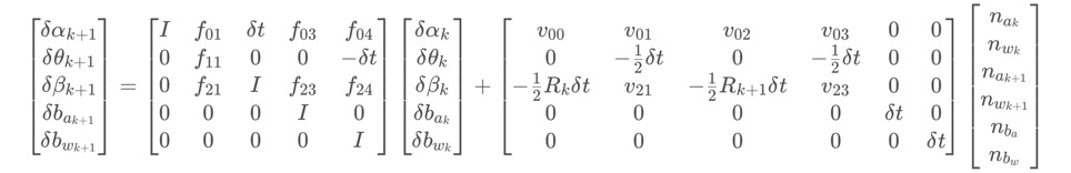
Jacobian's iterative formula는 다음과 같다.
이 형태는 VINS에 많이 나타나는데, 하나는 여기에 나타나있고, 나머지 세 개는 back-end optimization에서 나타난다.
covatiance iteration formula는 다음과 같다.
이 covariance matrix 는 back-end optimization의 IMU part에서 information matrix로 쓰인다.
noise를 나타내는 diagonal covariance matrix Q 는 다음과 같다.
3-(1). midPointIntegration()
해당 부분은 2-(5) 에서 본 코드의 뒷 내용이다.
1
2
3
4
5
6
7
8
9
10
11
12
13
14
15
16
17
18
19
20
21
22
23
24
25
26
27
28
29
30
31
32
33
34
35
36
37
38
39
40
41
42
43
44
45
46
47
48
49
50
51
52
53
54
|
if(update_jacobian)
{
Vector3d w_x = 0.5 * (_gyr_0 + _gyr_1) - linearized_bg;
Vector3d a_0_x = _acc_0 - linearized_ba;
Vector3d a_1_x = _acc_1 - linearized_ba;
Matrix3d R_w_x, R_a_0_x, R_a_1_x;
R_w_x<<0, -w_x(2), w_x(1),
w_x(2), 0, -w_x(0),
-w_x(1), w_x(0), 0;
R_a_0_x<<0, -a_0_x(2), a_0_x(1),
a_0_x(2), 0, -a_0_x(0),
-a_0_x(1), a_0_x(0), 0;
R_a_1_x<<0, -a_1_x(2), a_1_x(1),
a_1_x(2), 0, -a_1_x(0),
-a_1_x(1), a_1_x(0), 0;
MatrixXd F = MatrixXd::Zero(15, 15);
F.block<3, 3>(0, 0) = Matrix3d::Identity();
F.block<3, 3>(0, 3) = -0.25 * delta_q.toRotationMatrix() * R_a_0_x * _dt * _dt +
-0.25 * result_delta_q.toRotationMatrix() * R_a_1_x * (Matrix3d::Identity() - R_w_x * _dt) * _dt * _dt;
F.block<3, 3>(0, 6) = MatrixXd::Identity(3,3) * _dt;
F.block<3, 3>(0, 9) = -0.25 * (delta_q.toRotationMatrix() + result_delta_q.toRotationMatrix()) * _dt * _dt;
F.block<3, 3>(0, 12) = -0.25 * result_delta_q.toRotationMatrix() * R_a_1_x * _dt * _dt * -_dt;
F.block<3, 3>(3, 3) = Matrix3d::Identity() - R_w_x * _dt;
F.block<3, 3>(3, 12) = -1.0 * MatrixXd::Identity(3,3) * _dt;
F.block<3, 3>(6, 3) = -0.5 * delta_q.toRotationMatrix() * R_a_0_x * _dt +
-0.5 * result_delta_q.toRotationMatrix() * R_a_1_x * (Matrix3d::Identity() - R_w_x * _dt) * _dt;
F.block<3, 3>(6, 6) = Matrix3d::Identity();
F.block<3, 3>(6, 9) = -0.5 * (delta_q.toRotationMatrix() + result_delta_q.toRotationMatrix()) * _dt;
F.block<3, 3>(6, 12) = -0.5 * result_delta_q.toRotationMatrix() * R_a_1_x * _dt * -_dt;
F.block<3, 3>(9, 9) = Matrix3d::Identity();
F.block<3, 3>(12, 12) = Matrix3d::Identity();
//cout<<"A"<<endl<<A<<endl;
MatrixXd V = MatrixXd::Zero(15,18);
V.block<3, 3>(0, 0) = 0.25 * delta_q.toRotationMatrix() * _dt * _dt;
V.block<3, 3>(0, 3) = 0.25 * -result_delta_q.toRotationMatrix() * R_a_1_x * _dt * _dt * 0.5 * _dt;
V.block<3, 3>(0, 6) = 0.25 * result_delta_q.toRotationMatrix() * _dt * _dt;
V.block<3, 3>(0, 9) = V.block<3, 3>(0, 3);
V.block<3, 3>(3, 3) = 0.5 * MatrixXd::Identity(3,3) * _dt;
V.block<3, 3>(3, 9) = 0.5 * MatrixXd::Identity(3,3) * _dt;
V.block<3, 3>(6, 0) = 0.5 * delta_q.toRotationMatrix() * _dt;
V.block<3, 3>(6, 3) = 0.5 * -result_delta_q.toRotationMatrix() * R_a_1_x * _dt * 0.5 * _dt;
V.block<3, 3>(6, 6) = 0.5 * result_delta_q.toRotationMatrix() * _dt;
V.block<3, 3>(6, 9) = V.block<3, 3>(6, 3);
V.block<3, 3>(9, 12) = MatrixXd::Identity(3,3) * _dt;
V.block<3, 3>(12, 15) = MatrixXd::Identity(3,3) * _dt;
//step_jacobian = F;
//step_V = V;
jacobian = F * jacobian;
covariance = F * covariance * F.transpose() + V * noise * V.transpose();
}
| cs |
Vector3d w_x = 0.5 * (_gyr_0 + _gyr_1) - linearized_bg;
Vector3d a_0_x = _acc_0 - linearized_ba;
Vector3d a_1_x = _acc_1 - linearized_ba;
Matrix3d R_w_x, R_a_0_x, R_a_1_x;
R_w_x<<0, -w_x(2), w_x(1),
w_x(2), 0, -w_x(0),
-w_x(1), w_x(0), 0;
R_a_0_x<<0, -a_0_x(2), a_0_x(1),
a_0_x(2), 0, -a_0_x(0),
-a_0_x(1), a_0_x(0), 0;
R_a_1_x<<0, -a_1_x(2), a_1_x(1),
a_1_x(2), 0, -a_1_x(0),
-a_1_x(1), a_1_x(0), 0;
위 내용은 아래 수식에서 각 요소를 정의하기 위한 값들을 만드는 과정이다.
MatrixXd F = MatrixXd::Zero(15, 15);
F.block<3, 3>(0, 0) = Matrix3d::Identity();
F.block<3, 3>(0, 3) = -0.25 * delta_q.toRotationMatrix() * R_a_0_x * _dt * _dt +
-0.25 * result_delta_q.toRotationMatrix() * R_a_1_x * (Matrix3d::Identity() - R_w_x * _dt) * _dt * _dt;
F.block<3, 3>(0, 6) = MatrixXd::Identity(3,3) * _dt;
F.block<3, 3>(0, 9) = -0.25 * (delta_q.toRotationMatrix() + result_delta_q.toRotationMatrix()) * _dt * _dt;
F.block<3, 3>(0, 12) = -0.25 * result_delta_q.toRotationMatrix() * R_a_1_x * _dt * _dt * -_dt;
F.block<3, 3>(3, 3) = Matrix3d::Identity() - R_w_x * _dt;
F.block<3, 3>(3, 12) = -1.0 * MatrixXd::Identity(3,3) * _dt;
F.block<3, 3>(6, 3) = -0.5 * delta_q.toRotationMatrix() * R_a_0_x * _dt +
-0.5 * result_delta_q.toRotationMatrix() * R_a_1_x * (Matrix3d::Identity() - R_w_x * _dt) * _dt;
F.block<3, 3>(6, 6) = Matrix3d::Identity();
F.block<3, 3>(6, 9) = -0.5 * (delta_q.toRotationMatrix() + result_delta_q.toRotationMatrix()) * _dt;
F.block<3, 3>(6, 12) = -0.5 * result_delta_q.toRotationMatrix() * R_a_1_x * _dt * -_dt;
F.block<3, 3>(9, 9) = Matrix3d::Identity();
F.block<3, 3>(12, 12) = Matrix3d::Identity();
위 내용은 아래 수식의 우항의 F matrix를 나타내며, 각 요소는 3x3 크기이다.
MatrixXd V = MatrixXd::Zero(15,18);
V.block<3, 3>(0, 0) = 0.25 * delta_q.toRotationMatrix() * _dt * _dt;
V.block<3, 3>(0, 3) = 0.25 * -result_delta_q.toRotationMatrix() * R_a_1_x * _dt * _dt * 0.5 * _dt;
V.block<3, 3>(0, 6) = 0.25 * result_delta_q.toRotationMatrix() * _dt * _dt;
V.block<3, 3>(0, 9) = V.block<3, 3>(0, 3);
V.block<3, 3>(3, 3) = 0.5 * MatrixXd::Identity(3,3) * _dt;
V.block<3, 3>(3, 9) = 0.5 * MatrixXd::Identity(3,3) * _dt;
V.block<3, 3>(6, 0) = 0.5 * delta_q.toRotationMatrix() * _dt;
V.block<3, 3>(6, 3) = 0.5 * -result_delta_q.toRotationMatrix() * R_a_1_x * _dt * 0.5 * _dt;
V.block<3, 3>(6, 6) = 0.5 * result_delta_q.toRotationMatrix() * _dt;
V.block<3, 3>(6, 9) = V.block<3, 3>(6, 3);
V.block<3, 3>(9, 12) = MatrixXd::Identity(3,3) * _dt;
V.block<3, 3>(12, 15) = MatrixXd::Identity(3,3) * _dt;
위 내용은 아래 수식의 오른쪽 매트릭스 V를 의미하며, V 행렬안의 각 요소는 3x3 크기이다.
jacobian = F * jacobian;
covariance = F * covariance * F.transpose() + V * noise * V.transpose();
위 내용은 아래 수식을 나타낸다. 차후에 사용하기 위해 jacobian과 covariance를 업데이트 시킨다.
4. IntegrationBase class
vins_setimator/src/factor/integration_base.h 에 존재하는 IntegrationBase class에 대해 알아보자. IMU 관련하여 자주 사용되는 부분이다.
4-(1). Constructor
1
2
3
4
5
6
7
8
9
10
11
12
13
14
15
16
|
IntegrationBase(const Eigen::Vector3d &_acc_0, const Eigen::Vector3d &_gyr_0,
const Eigen::Vector3d &_linearized_ba, const Eigen::Vector3d &_linearized_bg)
: acc_0{_acc_0}, gyr_0{_gyr_0}, linearized_acc{_acc_0}, linearized_gyr{_gyr_0},
linearized_ba{_linearized_ba}, linearized_bg{_linearized_bg},
jacobian{Eigen::Matrix<double, 15, 15>::Identity()}, covariance{Eigen::Matrix<double, 15, 15>::Zero()},
sum_dt{0.0}, delta_p{Eigen::Vector3d::Zero()}, delta_q{Eigen::Quaterniond::Identity()}, delta_v{Eigen::Vector3d::Zero()}
{
noise = Eigen::Matrix<double, 18, 18>::Zero();
noise.block<3, 3>(0, 0) = (ACC_N * ACC_N) * Eigen::Matrix3d::Identity();
noise.block<3, 3>(3, 3) = (GYR_N * GYR_N) * Eigen::Matrix3d::Identity();
noise.block<3, 3>(6, 6) = (ACC_N * ACC_N) * Eigen::Matrix3d::Identity();
noise.block<3, 3>(9, 9) = (GYR_N * GYR_N) * Eigen::Matrix3d::Identity();
noise.block<3, 3>(12, 12) = (ACC_W * ACC_W) * Eigen::Matrix3d::Identity();
noise.block<3, 3>(15, 15) = (GYR_W * GYR_W) * Eigen::Matrix3d::Identity();
}
| cs |
생성자에서는 다음과 같은 내용이 초기화된다.
1. acc_0 : time i 에 대한 가속도 값이다. _acc_0 값으로 초기화된다.
2. gyr_0 : ime i에 대한 회전 가속도 값이다. _gyr_0 값으로 초기화된다.
3. linearized_ba : 가속도 bias 값이다.
4. linearized_bg : 회전 가속도 bias 값이다.
5. linearized_acc : bk 프레임에 대한 가속도 값이다.
6. linearized_gry : bk 프레임에 대한 회전 가속도 값이다.
7. Jacobian : 15x15 크기의 identity matrix로 초기화된다.
8. covariance : 15x15 크기의 zero matrix로 초기화된다.
9. sum_dt : 누적된 시간 값이다.
10. delta_p : 위치
11. delta_q : 회전
12. delta_v : 속도
13. noise : 18x18 matrix로 yaml file로 부터 읽어들인 parameters를 이용해 IMU noise를 초기화한다.
4-(2). Propagate
propagate은 bk와 bk_1 사이에서 time i 에서 time i+1 단위로 PVQ propagation과 error transmission 목적으로 사용된다.
1
2
3
4
5
6
7
8
9
10
11
12
13
14
15
16
17
18
19
20
21
22
23
24
25
26
27
28
29
|
void propagate(double _dt, const Eigen::Vector3d &_acc_1, const Eigen::Vector3d &_gyr_1)
{
dt = _dt;
acc_1 = _acc_1;
gyr_1 = _gyr_1;
Vector3d result_delta_p;
Quaterniond result_delta_q;
Vector3d result_delta_v;
Vector3d result_linearized_ba;
Vector3d result_linearized_bg;
midPointIntegration(_dt, acc_0, gyr_0, _acc_1, _gyr_1, delta_p, delta_q, delta_v,
linearized_ba, linearized_bg,
result_delta_p, result_delta_q, result_delta_v,
result_linearized_ba, result_linearized_bg, 1);
//checkJacobian(_dt, acc_0, gyr_0, acc_1, gyr_1, delta_p, delta_q, delta_v,
// linearized_ba, linearized_bg);
delta_p = result_delta_p;
delta_q = result_delta_q;
delta_v = result_delta_v;
linearized_ba = result_linearized_ba;
linearized_bg = result_linearized_bg;
delta_q.normalize();
sum_dt += dt;
acc_0 = acc_1;
gyr_0 = gyr_1;
}
| cs |
시간 dt와 가속도 acc, 회전 가속도 gyr를 파라미터로 받아
midPointIntegration() 함수를 통하여 PVQ와 bias를 갱신시킨 후,
갱신된 변수들을 과거 변수로 만드는 과정을 수행한다.
4-(3). repropagate
repropagate() 는 propagate() 보다 낮은 frequency로 실행되며,bk와 bk+1 간의 PVQ propagation correction 및 error transmission correction을 진행한다.
1
2
3
4
5
6
7
8
9
10
11
12
13
14
15
|
void repropagate(const Eigen::Vector3d &_linearized_ba, const Eigen::Vector3d &_linearized_bg)
{
sum_dt = 0.0;
acc_0 = linearized_acc;
gyr_0 = linearized_gyr;
delta_p.setZero();
delta_q.setIdentity();
delta_v.setZero();
linearized_ba = _linearized_ba;
linearized_bg = _linearized_bg;
jacobian.setIdentity();
covariance.setZero();
for (int i = 0; i < static_cast<int>(dt_buf.size()); i++)
propagate(dt_buf[i], acc_buf[i], gyr_buf[i]);
}
| cs |
보면 sum_dt를 0으로 초기화시키고, propagation을 통해 얻은 가속도, 회전 가속도 값을 acc_0, gyr_0 로 만들고, PVQ를 초기화시키고, bias 값들도 갱신하고, jacobian과 covariance도 초기화한 후,
propagate를 쌓인 dt, acc, gyro 만큼 다시 반복하는 것을 확인할 수 있다.
댓글 없음:
댓글 쓰기